 Connections
Here the Input/Output ports of the autopilot can be configured. Depending on the configurable port selected, the user will need to provide different parameters.
Each connection is associated with a specific pin number. For more details see the Pinout - Hardware Installation section of the 1x Hardware Manual.
ADC
ADC stands for Analog-to-Digital Converter. This connection is used by analog sensors. These sensors provide a voltage readout that needs to be converted into the actual measured variable, e.g. temperature, fuel volume, etc.
Autopilot 1x is equipped with 5 connections of this kind. Every ADC connection that is set requires an integer variable associated where the voltage readout will be stored. The maximum voltage of the ADC connection is 3.3 V.
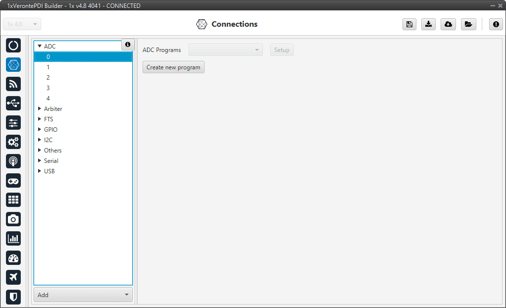
ADC panel
To convert the input ADC value to the physical variable it represents, the user needs to create a new program. See more information about programs in the Block Programs section of this manual.
Application example
Let us consider a Fuel Level Sensor whose datasheet provides a direct relation of the voltage readout and the fuel volume (in L) through the polynomial \(y=-0.0498x^4+0.3002x^3-0.3083x^2+1.2123x+0.15\), where \(y\) is the fuel volume and \(x\) is the sensor voltage.
Creating a new program, the above equation can be reproduced. An example of how to do it is presented below.
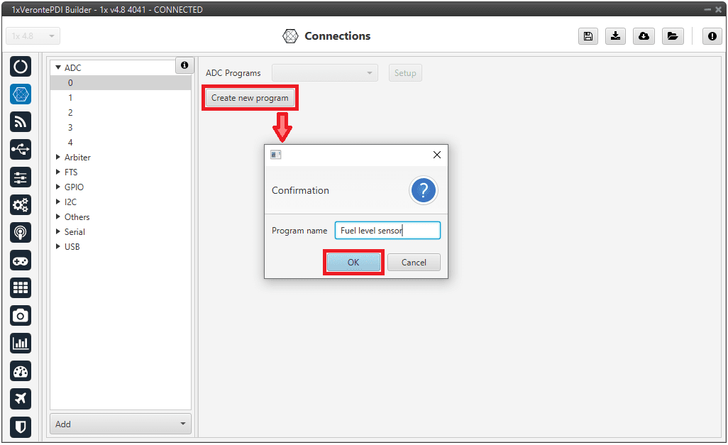
Create ADC program
When the ADC program is created, a default block program is also created.
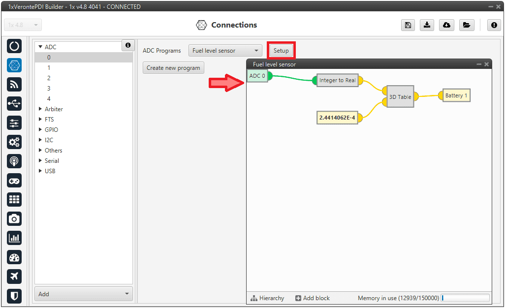
ADC default program
Now, the program has to be customized for this application. See more information about programs in the Block Programs section of this manual.
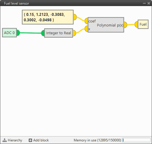
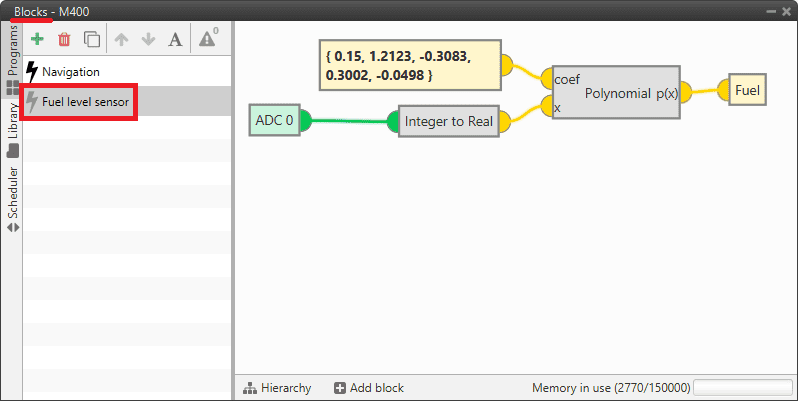
ADC conversion for a Fuel Level Sensor
The fuel remaining in the tank is saved in a user variable, which can be used for displaying or warning purposes.
Note
The ADC variable is first converted from integer to real, and then the polynomial is applied.
This program can now be modified by clicking in ‘Setup’ in this menu or in the Block Programs menu.
ADC program in Block Programs
Arbiter
Pins 45 and 46 are dedicated pins to allow the UART communication with the Safety micro Controller (SuC). This microcontroller is in charge of monitoring the state of the main microcontroller and providing the Flight Termination Signals (FTS).
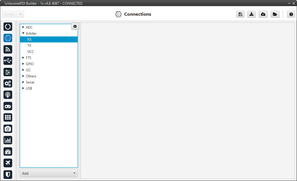
Arbiter panel
FTS
The FTS (Flight Termination System) is a signal that is activated when a sytem error occurs (System Error bit is False). There is a group of bits that, when failed, cause the system error. To see more about the conditions that make the system error happen, go to Activation System Error bits section of the 1x Software Manual.
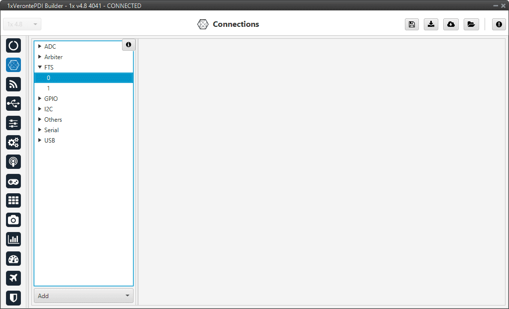
FTS panel
Pins 42 and 43 are related to the FTS:
Pin 42: Deadman signal from comicro, monitors main MPU encoding its product-level bit. This signal is a square wave at [100,125] Hz. It can be higher at rebooting (about 300-400Hz) but should never be less than 100Hz.
Pin 43: !SystemOK Bit. 0 when Ok (no failure detected) and 1 (high, 3.3 V) when an error is detected. This pin goes high if the deadman signal sent by the MPU (main processor unit) is lower than 63Hz. That means there is a critical error.
GPIO
Output pins produce PWM or GPIO signals that are used to move the different servos and actuators of the platform.
A GPIO (General Purpose Input/Output) is a generic pin that can be configured as an input or output pin. When this option is configured as an output pin, the value sent will be different from the one sent if it was a PWM.
GPIO pins admit up to 4 different states:
ON: A continuous signal of value 1, made by 3.3V.
OFF: A continuous signal of value 0, made by Ground.
PULSE ON: A single pulse of value 1, with a width specified in seconds.
PULSE OFF: A single pulse of value 0, with a width specified in seconds.
The configuration of the pin output value is done with an Output action in the Automations menu.
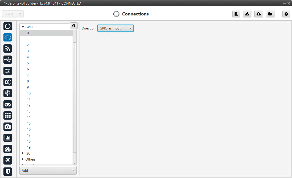
GPIO panel
Direction: Defines GPIO as an input or output.
Autopilot 1x admits up to 20 I/O PWM/GPIO signals. To configure a pin as GPIO after it has been changed to PWM, click Add and select GPIO:
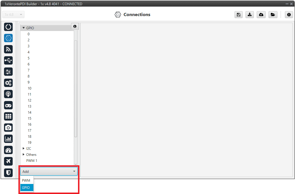
Add GPIO
Note
When a pin is added as GPIO, it is disabled as PWM and enabled as GPIO. Hence, in the GPIO panel of Veronte menu, the “Function” parameter shall change to “Mux 0”.
I2C
I2C stands for Inter-Integrated Circuit bus. It is a bus interface connection protocol incorporated into devices for serial communication. It operates in 2 modes: master and slave.
I2C uses only 2 bi-directional open-drain lines for data communication called SDA and SCL. Both these lines are pulled high.
Pin 31 - SCL: Clock line for I2C bus (0.3V to 3.3V), it carries the clock signal.
Pin 32 - SDA: Data line for I2C bus (0.3V to 3.3V), transfer of data takes place through this pin.
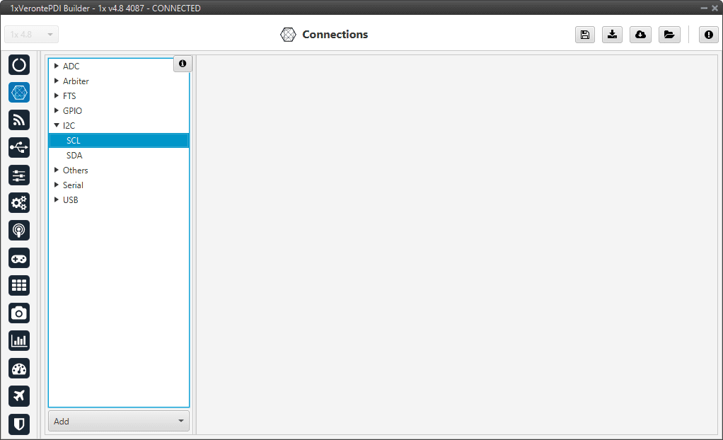
I2C panel
Tip
These pins are very useful for forcing maintenance mode. For more information, refer to the Using the I2C pins to enter in maintenance mode - Troubleshooting section of the 1x Hardware Manual.
Others
GND: Ground.
Power.
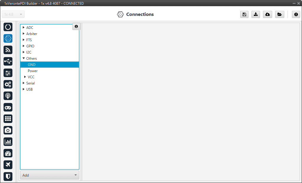
Others panel
PWM
Output pins produce PWM or GPIO signals that are used to move the different servos and actuators of the platform.
The acronym PWM corresponds to Pulse Width Modulation. 1x sends a pulse with a certain width that is received by the servo/actuator, and according to the width of such pulse, it changes its behavior. A wide pulse will correspond to a big movement and a narrow one to a small movement.
By default, all PWM/GPIO pins are configured as GPIO output. So, to configure them as PWM, it is necessary to click Add:
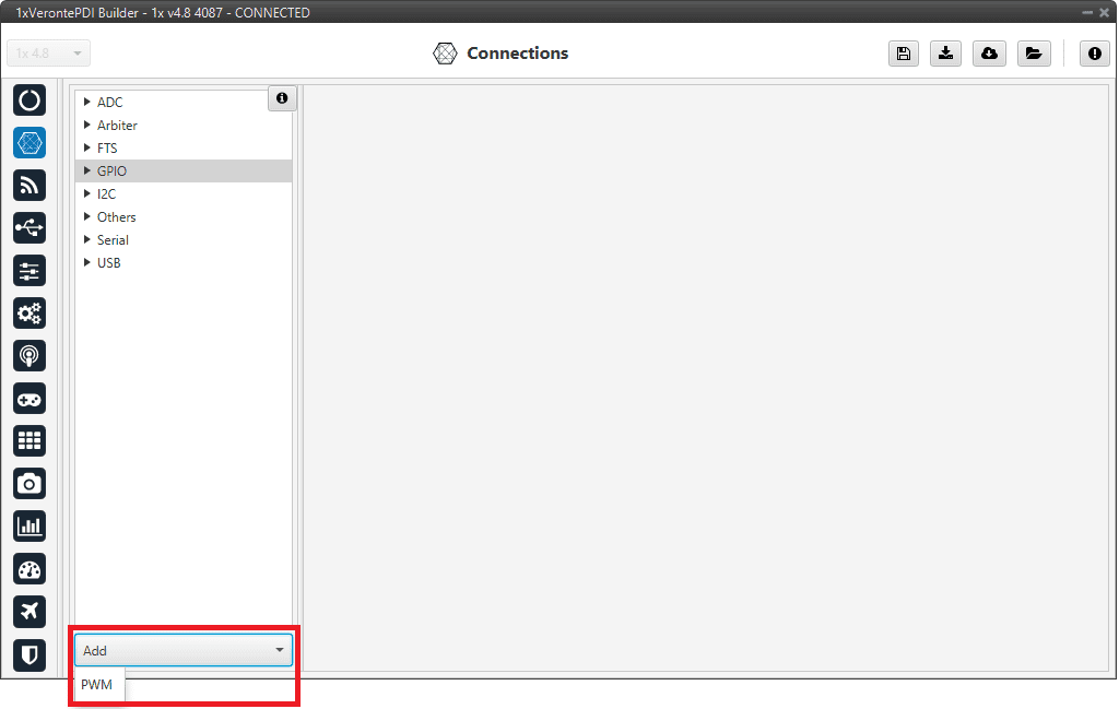
Add PWM
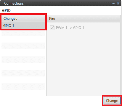
Then, select the GPIO pin the user want to change to PWM. As can be seen, pins are interchangeable.
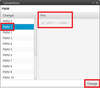
PWM change
Note
When a pin is added as PWM, it is disabled as GPIO and enabled as PWM. Hence, in the GPIO panel of Veronte menu, the “Function” parameter shall change to “Mux 1”.
As shown in the image below, the GPIO 1 output is now missing as it has been changed to a PWM output.
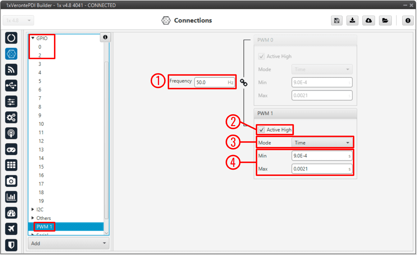
PWM panel
In this menu the following parameters can be configured:
Frequency: PWM output frequency. This option determines the period of the pulses sent by the autopilot. The PWM is built in pairs inside the autopilot, and that is why the frequency is indicated in pairs, i.e when the frequency of PWM 0 is changed, the one of PWM 1 also changes. The following table shows the PMW pairs as configured in Autopilot 1x.
PWM 0
PWM 1
PWM 2
PWM 3
PWM 4
PWM 5
PWM 6
PWM 7
PWM 8
PWM 9
PWM 10
PWM 11
PWM 12
PWM 13
PWM 14
PWM 15
PWM 16
PWM 17
PWM 18
PWM 19
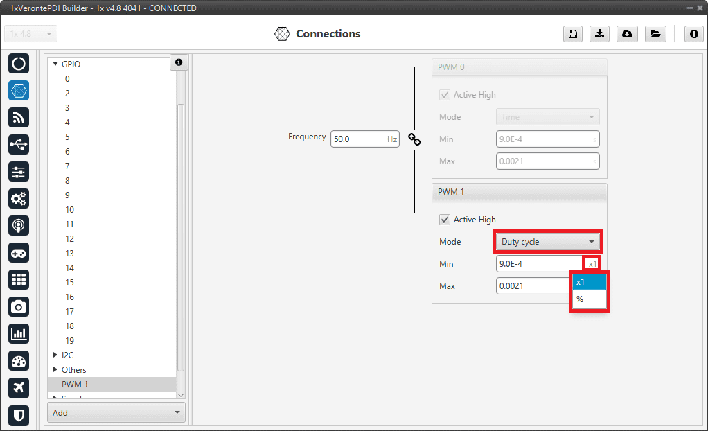
Active High: Polarity high or low (high if enabled).
Mode: The available options are Time and Duty cycle.
Time: The values indicated in Min and Max parameters are expressed in time units.
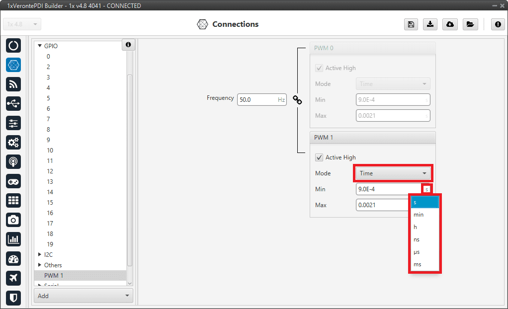
PWM panel - Time units
Duty cycle: This option is a different way of indicating the pulse width. Now the value indicated in Min and Max parameters is a percentage which corresponds to the relation between the pulse width over the total period of the sent signal.
So a 100% duty cycle will correspond to a signal with a constant value of 1, while a 0% duty cycle implies a constant signal with value 0. Between this two extremes, the pulse width can vary as in the examples shown in the following figure.
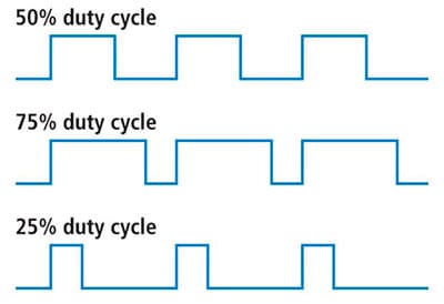
Duty cycle
Min/Max: These parameters are the pulse width values that will make the servo/actuator go to its lowest/highest position. It will be the output when the PWM message specifies 0/4095.
As an example let’s consider the servo of an aircraft elevator, a pulse sent by Autopilot 1x of 0.9 ms will correspond with the lowest point of the servo range (-30 degrees for example). On the other hand, a pulse of 2.1 ms will make the servo go to its top position (for example 30 degrees).
Summary
A PWM is a signal which consists of a series of pulses having a width determined by a percentage over a range specified by the parameters Min and Max. On the other hand, the GPIO is a signal with a constant value (1,0) or with a single pulse (1,0).
Serial
Two serial interfaces are available with Autopilot 1x, 1 port RS-232 and 1 port RS-485, however more can be added by using a CEX or MEX. Each one of the serial interfaces is associated with a set of pins. To configure these serial ports, go to Serial panel in the Input/Output menu.
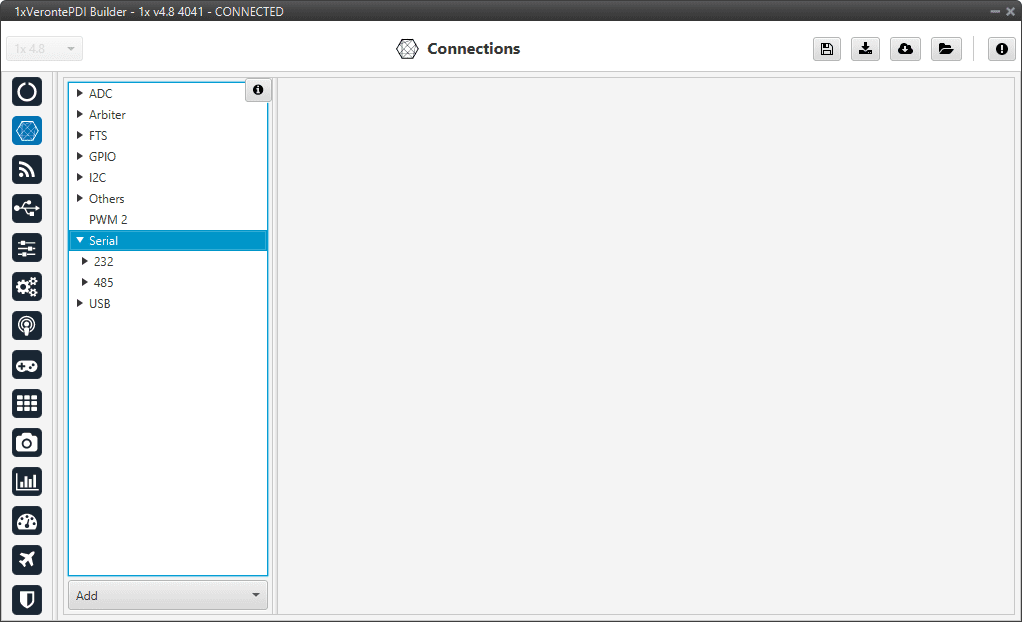
Serial panel
USB
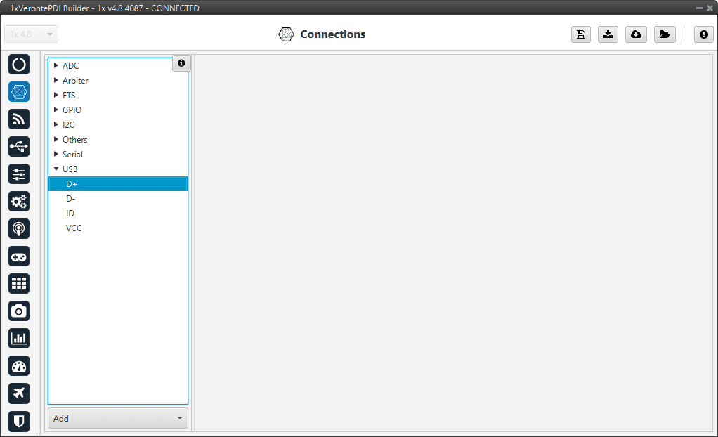
USB panel